
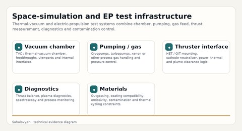
Chamber
- volume and access
- feedthroughs and viewports
- internal fixtures
- clean assembly
TVAC, pumping, gas-flow, diagnostics and materials compatibility.
The useful question is not only nominal pumping speed. Effective speed at the chamber and the process gas load define operating pressure during a thruster or cathode test.
| Subsystem | Critical check | Record |
|---|---|---|
| Chamber | leak tightness, cleanliness, port geometry, conductance | helium leak test, pressure-rise curve, port map |
| Pumping | effective speed for xenon or process gas | pump curve, conductance estimate, gas-load test |
| Thermal | temperature range, gradients, shroud/fixture interaction | thermal map, ramp/soak logs |
| Diagnostics | line of sight, feedthroughs, OES, electrical noise | diagnostic layout and signal records |
| Contamination | outgassing, deposits, optical access, exposed surfaces | cleaning records, witness samples, visual inspection |
| Test condition | Scientific issue | Record | Risk if missing |
|---|---|---|---|
| Empty-chamber base pressure | Only describes chamber without operational gas load. | Pump-down and pressure-rise curves. | Overstates readiness for EP operation. |
| Xenon / process gas flow | Defines operating pressure and plume / diagnostic environment. | Gas-flow calibration, P ≈ Q_gas / S_eff estimate. | Diagnostics interpreted under wrong pressure assumption. |
| Diagnostic geometry | Line of sight, contamination and signal interpretation depend on layout. | Port map, witness samples, diagnostic scheme. | Good sensor data but unclear environment. |
| Material exposure | Outgassing, contamination and optical property drift can alter test results. | Material list, bake history, witness records. | Contamination treated as unrelated noise. |